Tool Shanks - Styles & Applications
Spindle Selection
What type of spindles are available on machine tools, and which is best for me? Over the past five to six decades, machine tool builders have developed many varied sizes and styles of machine tool tapers to hold the tool holders and cutting tools they want their machines to utilize. They look at multiple factors such as rigidity, RPM/Speed of spindle, size, and overall performance desired between machine control, accuracy of machine, and speed of table/head feed rate. Over the past three decades, the metal cutting industry has settled on five to six different spindle connections and machine tool builders design their equipment using any one of these taper technologies as it best suits their machine design.
NMTB

Old technology mainly used on manual equipment and large boring mills where automatic tool changes are not needed.
CAT40/CAT50
The ANSI/ASME B5.50 was designed in the early 1980's for use with automatic tool changing systems in machines. This replaced the manual tool changes with automatic tool change arms and tool carousel storage. This steep taper design was produced to help the machine tool builders and the metal working end-users to standardize the spindle connection since many of the machine tool builders in the 1970's and early 1980's had designed their own connection thus making it difficult for the manufacturers to standardize their equipment as they purchased new machines and tooling. The steep taper design allows for more rigid applications when heavy radial loads are part of the machining process. This design has some limitations regarding spindle RPM as high RPM machining tends to cause taper “bell-mouthing” at the spindle's largest opening allowing increased tool TIR growth and loss of machine taper/tool holder taper contact. CAT is a largely a North American spindle connection compared to balance of the world.
BT30/40/50
MAS403 spindle connection. Originally a standard design on all Japanese designed and produced machine tools. It has slightly better “balanced by design” features and the tool change arm allows for faster tool changes between spindle and tool storage system. Uses the same steep taper design that the ANSI/ASME style offers but allows higher spindle RPM due the “balanced by design” flange. Similar performance as the ANSI/ASME style where heavy radial loads are used in many machining processes.
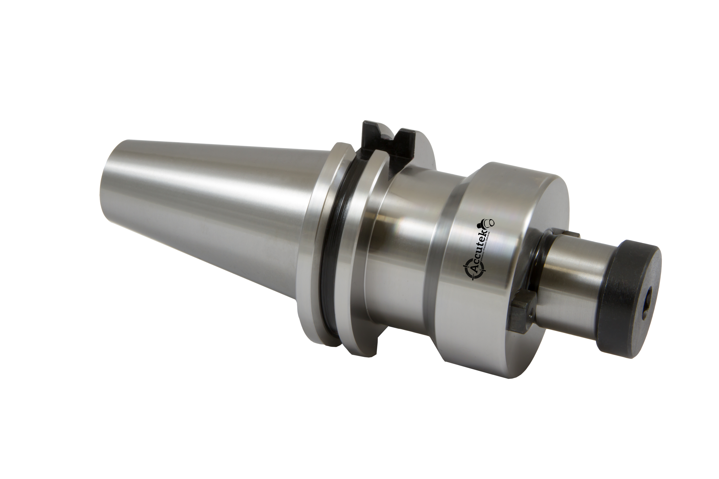
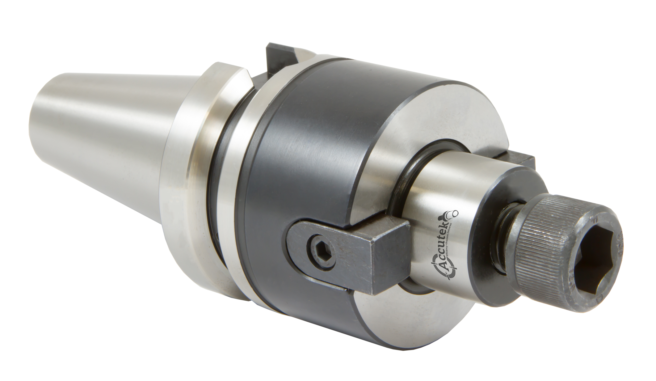
BT & CAT
Face Contact

Face Contact designs, which were developed by Daishowa Seiki Co. in 1994 under US Patent 5352073, took the benefits of the MAS 403 and ANSI/ASME designs but removed the “weakness” from higher RPM machining by utilizing a face contact between the flange of the tool holder and the spindle face of the machine tool spindle. This additional contact surface allows more rigidity because of the larger “footprint” the spindle face contact offers. This large diameter of contacts increases the “leverage point” between spindle taper, spindle face, tool taper, and tool flange face. Excellent design where long-length tools and/or large diameter tools benefit from additional tool/taper contact for accuracy and rigidity. While this design is like the BT-MAS and CAT-ANSI, interchanging styles of tapers in a face contact spindle is not recommended. Accutek follows the expired US Patent 5352073 to maintain the integrity of the design as our AccuPlus™ product.
HSK – DIN 69893
A, C, E, and F styles
HSK means “hollow shank” and uses a drawbar that pulls the taper into the machine using internal gripping vs. the external drawbar gripping that steep taper designs use with a retention knob. While this is a spindle connection for metal working machines like the steep taper designs, this design allows for much higher spindle RPM machining because of the spindle/drawbar, and connection design. The “low profile design” and balanced orientation slots allows for a much higher spindle RPM without the spindle opening “bell-mouthing” seen in the steep taper designs. HSK also uses the face contact to increase tool holder rigidity for radial loads. HSK does require a change in “machine programming culture”. With ANSI and MAS403 designs, heavy radial loads at lower spindle RPMs is the normal practice. With the HSK shank such heavy radial loads are handled differently by increasing spindle RPM, lighter chip loads on cutting tools, and an overall increase in machining metal removal rates. By reducing chip load and increasing spindle RPM, most of the “heat” created during the machining process goes with the chip/swarf and not into the cutting tool or work piece material. Better tool life, better work piece accuracy, and better part finishes can be achieved using HSK spindle technology over steep taper designs. As HSK spindle RPM increases, HSK shank tooling tapers and diameters can “shrink” in sizes to better match the machining processes and high spindle RPM demands for high tool assembly balance needs. HSK shanks are available in sizes 20 taper through 125 (number indicates OD size of flange diameter). Styles of flanges can also be changed to increase balance of holder by changing from “A” or ”C” styles to “E” or “F” styles.
ISO26623-1 CAPTO®
ISO26622-1 KM®
ISO26623-1 - PTI
In the mid-1990s the new machine technology was the Multi-Tasking machining center or the Mill-Turn machining centers. This new machining technology required a spindle connection that not only could rotate for rotational machining applications like milling, drilling, tapping, etc. but also maintain a static or stationary position for turning – thus the multi-tasking or mill-turn names. Rotational tool machining presents a specific set or forces that static or stationary turning does not present. Conversely, static or stationary turning presents machining forces not seen in rotation tooling applications. This required new spindle connect designs to allow the “complete” machining process with a single style tool holder and machine connection. After several attempts by cutting tool manufacturers to develop the “best” spindle/tool holder interface that performs well in both rotating and static applications, two designs have become the primary choices by machine tool builders and metal working customers – ISO 26622-1 KM® tool shank and ISO26623-1 CAPTO®¹ shank. The KM®² shank was an original design by Kennametal Inc. and CAPTO® was an original design by Sandvik Coromant. Both designs achieve the desired results of rigidity, quick tool changes, accuracy, and strength in static operations and rotational operations. The style preference is up to the individual's comfort.
ISO26622-1 - KTI
Determining your spindle connection for your next machine tool purchase depends on your comfort level with new spindle technology, need for increased machining capabilities, and type of work you plan to process through the new machine. While there are advantages with Steep Taper designs as well as HSK Taper designs, you will need to match those advantages to your specific machining needs. Most important fact about spindle and tool connection selection – TIR (Total Indicator Run-out) is the primary consideration. Quality, price, and accuracy of the tool holder are all considerations, but for every .0001 of TIR away from the tool assembly center-line, 10% of your cutting tool life is lost due to uneven cutting tool edge material loads. TIR can be measured where the cutting tool shank and tool holder meet but the true assembly TIR should be measured at the tip of the cutting tool where the dimensional accuracy of your tool assembly and cutting parameters are determined.